

 Home
Home
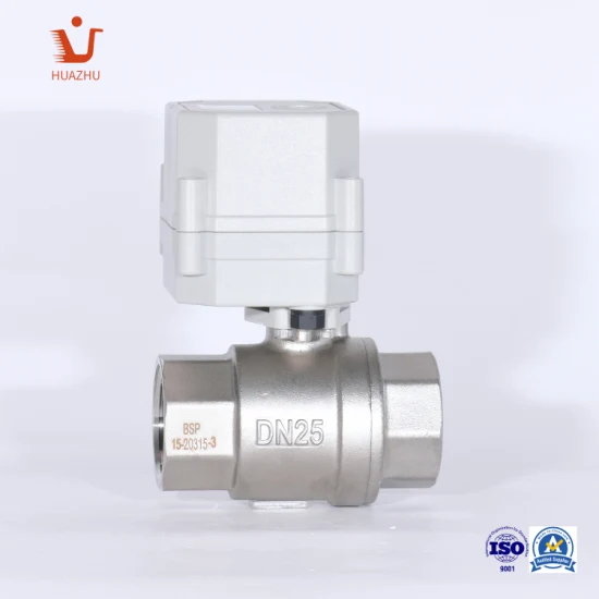
Automatic Electric Water Shut Ball Valve
ELECTRIC STAINLESS STEEL304 BALL VALVE Technical Parameters: Wiring diagram CR201 Wiring Diagram ( 2 wires control ) RD
Send your inquiryDESCRIPTION
Basic Info
| Model NO. | T32-S2-C |
| Pressure | Ordinary Temperature |
| Power Supply | DC Solenoid Valve |
| Usage | Flow Control |
| Application | Water Industrial Usage |
| Transport Package | Wooden Case |
| Trademark | HUAZHU |
| Origin | Ningbo |
| HS Code | 8481901000 |
| Production Capacity | 50000PCS/Monthly |
Product Description
ELECTRIC STAINLESS STEEL304 BALL VALVETechnical Parameters:
| Product size | NPT/BSP 1-1/4'' NPT/BSP 1-1/2' NPT/BSP2'' (Optional) |
| Maximum working pressure | 1.0MPa |
| Circulation medium | Fluid, air |
| Rated voltage | DC12V/AC/DC24/AC/DC9-35V/AC110-230V (Optional) |
| Wiring control methods | CR201/CR202/CR303/CR401/CR501/CR502/CR703/CR7-04 (Optional) |
| Static current | ≤150MA |
| Open/close time | ≤13S |
| Life time | 50000 times |
| Valve Body material | 304 Stainless steel |
| Actuator material | Engineering Plastics |
| Sealing material | EPDM & PTFE |
| Actuator rotation | 90° |
| Max. torque force | 10Nm |
| Cable Length | 0.5m,1.5m, (Optional) |
| Environment temperature | -15ºC~50ºC |
| Liquid temperature | 2ºC~90ºC |
| Manual override | No |
| Indicator | Yes |
| Protection class | IP67 |
Wiring diagram
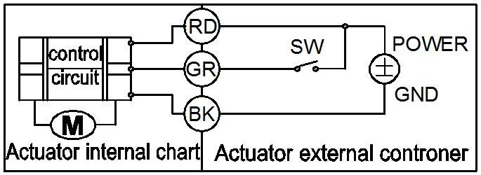
CR201 Wiring Diagram ( 2 wires control )
BK connect with positive, the RD connect with negative, the valve open, the actuator automatically power off after in place, the valve remains fully open position .
Suitable Working Voltage: DC12V/DC24V
Exceeding the working voltage is forbidden
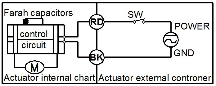
CR202 Wiring Diagram ( 2 wires control - Spring return in case of the power is failure)
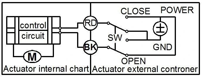
CR303 Wiring Diagram (3 wires control )
BK connect with negative
When the SW of GR closed, the valve OPEN, the actuator automatically power off after in place , remains fully closed position
·When the SW of GR open, the valve CLOSED, the actuator automatically power off after in place , remains fully open position.
Suitable Working Voltage: DC12V/AC/DC24V/AC/DC110V-230V
CR401 Wiring Diagram (4 wires control )
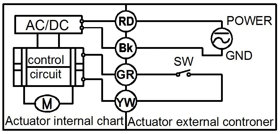
Exceeding the working voltage is forbidden
CR501 Wiring diagram ( with feedback signal)RD connect with positive, the BK connect with negative,the valve closed, the actuator automatically power off after in place .BK connect with positive, the RD connect with negative,the valve open, the actuator automatically power off after in place .BL & WT are connect when the valve open fully, YW & WT are connect when the valve closed fullySuitable Working Voltage::DC12V/DC24V
Exceeding the working voltage is forbidden
CR502 Wiring diagram ( with feedback signal)

CR703 Wiring Diagram ( 7 wires control with feedback signal )
RD& GR connect with positive, the BK connect with negative.
SW CLOSED, the valve OPEN, the actuator automatically power off after in place
SW OPEN, the valve CLOSED, the actuator automatically power off after in place.
BL & GY connect with the valve's fully open signal wiring
YW & WT connect with the valve's fully closed signal wiring.
Suitable Working Voltage: DC12V/AC/DC24V
Exceeding the working voltage is forbidden
CR704 Wiring Diagram ( 7 wires control with feedback signal )RD & BK are connected to the power, WT & YW are connected to the controlled wiring.
When the SW is closed , the valve open
When the SW is open , the valve closed
BL & GY connect with the valve's fully open signal wiring
YW & WT connect with the valve's fully closed signal wiring.
Suitable Working Voltage::AC110V-230V
Exceeding the working voltage is forbidden


